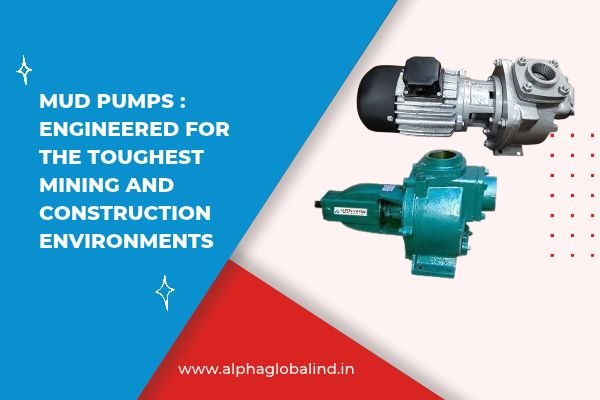
Across infrastructure projects, foundation piling sites, and mineral extraction zones throughout Gujarat and Western India, handling heavy fluid mixtures loaded with sand, gravel, clay, and rock slurry is a daily operational reality.
Whether recirculating bentonite drilling muds in urban foundation works or dewatering sediment-heavy pits in open-cast quarries, standard centrifugal pumps fail rapidly. Abrasive mineral particles act like internal grinding wheels, eroding impellers, scouring casing volutes, and destroying mechanical seal faces within hours of operation.
This is where true heavy-duty mud pumps (and slurry pumps) are required.
Engineering a pump to move heavy, solid-laden fluids requires a fundamental shift in design priority: hydraulics must be balanced with tribology—the science of friction, lubrication, and wear.
Here is a technical exploration of how industrial mud pumps are engineered to survive extreme solid-handling applications.
Understanding the Mechanics of Slurry Abrasion
To prevent catastrophic internal erosion, engineers must evaluate the nature of the fluid-solid mixture. The rate at which solids destroy pump components is governed by four primary variables:
Particle Hardness: Measured on the Mohs scale. Silica sand (hardness 7) and quartz will rapidly abrade mild steel and basic cast iron.
Particle Velocity: Wear rate is exponentially proportional to fluid velocity inside the pump. Doubling the impeller tip speed can increase wear rates by up to four times:
Wear Rate ∝ v³ to v⁴
Concentration by Weight (Cw): Higher percentage concentrations of solid particles increase particle impact frequency against internal walls.
Sharpness & Geometry: Angular, jagged crushed rock cuts metal surfaces much faster than rounded river sand.
[Horizontal Multi-Stage Fluid Acceleration]

      Suction End                                      Discharge End
    (Low Pressure)                                    (High Pressure)
   ===================================================================
   Inlet -> [Impeller 1] -> [Impeller 2] -> [Impeller 3] -> Boiler Out
            (Pressure +1)   (Pressure +2)   (Pressure +3)
   ===================================================================
         Continuous Head Accumulation Across Sequential Stages
The fluid enters the first stage impeller at low pressure, gains velocity, and passes through a stationary diffuser that converts that velocity into pressure. This pressurized fluid is then directed immediately into the suction eye of the next impeller stage.
The total pressure generated by the pump is the sum of the pressure increases across all stages. This design allows the pump to generate high heads efficiently within a compact, reliable footprint.
Key Structural Features of Heavy-Duty Mud Pumps
To resist this constant mechanical battering, heavy-duty mud pumps incorporate specific structural enhancements over conventional pumps:
1. Thick-Walled High-Chrome Alloys & Elastomers
Instead of standard gray cast iron, mud pump wet-end components (impellers, volute liners, and wear plates) are cast from Ni-Hard or 27% High-Chromium White Iron (heat-treated to hardness levels exceeding 600 BHN). This extreme material hardness prevents angular quartz grains from gouging into the matrix. For finer, sharp slurry particles, thick natural rubber or polyurethane liners are used to absorb impact energy and bounce particles off without eroding the wall.
2. Wide-Passage, Low-Vane Impeller Design
Standard water pumps use multi-vane, closed impellers with tight internal clearances designed for maximum hydraulic efficiency. Mud pumps use open or semi-open impellers with large internal passages and fewer vanes (typically 3 to 4). This allows large rocks, gravel chunks, and fibrous drilling muds to pass through without clogging the impeller eye.
3. Adjustable Axial Wear Plates
As the front face of the impeller slowly erodes over months of pumping sand, the clearance between the impeller and the front wear plate increases. This gap causes fluid to slip backward, dropping pump efficiency and accelerating localized wear. Industrial mud pumps feature external adjustment screws that allow maintenance technicians to push the wear plate back up against the impeller face without disassembling the wet end.
Preventing System Failure: Settling Velocity & Line Sizing
[Slurry Flow Regimes in Horizontal Pipe]

     High Velocity (Ideal):      [ *  *  *  *  *  *  * ] <-- Uniform Suspension

     Low Velocity (Dangerous):   [                     ] <-- Clear Water Top
                                 [ =================== ] <-- Settled Bed / Blockage
Engineering Best Practice:
Mechanical Seal Protection: The Expeller (Dynamic) Seal
Mud Pump Specification Matrix
| Component / Parameter | Standard Water Pump | Heavy-Duty Industrial Mud Pump |
| Impeller Material | Cast Iron / SS-304 | 27% High-Chrome Iron / Hardened Alloy |
| Volute Wall Thickness | Standard (6 – 10 mm) | Heavy Armor-Plated (20 – 40+ mm) |
| Solids Clearance | Up to 5 mm clean fluids | Up to 50 – 75+ mm spherical solids |
| Seal Configuration | Single Carbon/Ceramic | Expeller Seal / Tungsten-Carbide Heavy Duty |