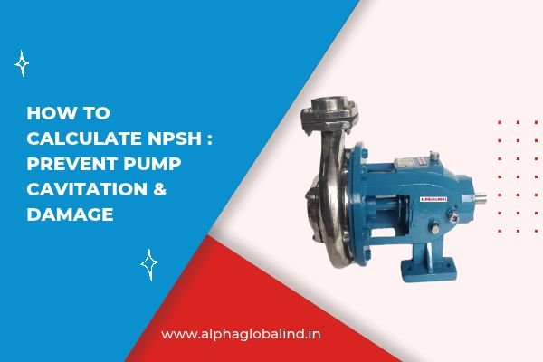
In chemical processing units, boiler plants, and water treatment facilities throughout Gujarat’s industrial centers—such as the manufacturing hubs in Vatva, Odhav, and Naroda—pump operators often encounter a mysterious, marble-rattling noise coming from inside their centrifugal pumps.
This noise is the signature sound of cavitation.
Cavitation occurs when the local liquid pressure inside a pump’s suction eye drops below the liquid’s vapor pressure. When this happens, microscopic vapor bubbles form instantly in the liquid stream. As these bubbles travel into the higher-pressure zones of the rotating impeller, they violently implode, generating micro-jets of liquid that strike the metal surface with shockwave forces exceeding 100,000 PSI.
To permanently eliminate cavitation, process engineers must master Net Positive Suction Head (NPSH) calculations during system design.
Here is a practical, step-by-step guide to calculating NPSH and optimizing your suction lines.
Understanding the Core Equation: NPSHa vs. NPSHr
To guarantee cavitation-free operation, you must balance two specific variables:
- NPSHr (NPSH Required): The minimum suction pressure required at the pump inlet to keep the fluid liquid. This value is determined by the pump manufacturer through laboratory testing and varies with flow rate and speed.
- NPSHa (NPSH Available): The actual pressure energy available in the piping system at the pump’s suction nozzle, determined entirely by your physical piping layout, tank elevation, and fluid properties.
The Golden Rule of Pump Design:
The Practical NPSHa Engineering Formula
To calculate the NPSH Available in your piping setup, use this standard engineering equation expressed in meters of liquid head:
NPSHa = Ha + Hs – Hf – Hvp
Where each variable represents a specific pressure component:
- Ha (Absolute Pressure Head): The absolute pressure acting on the surface of the liquid in the suction tank (converted to meters of head). For an open atmospheric tank at sea level, standard atmospheric pressure is approximately 10.33 meters of water column.
- Hs (Static Suction Head / Lift): The vertical distance between the liquid surface level and the pump impeller centerline.
- If the tank is above the pump (Flooded Suction), Hs is positive (+).
- If the tank is below the pump (Suction Lift), Hs is negative (-).
- Hf (Friction Head Loss): The cumulative friction pressure loss in meters caused by pipes, elbows, valves, strainers, and fittings in the suction line at the design flow rate.
- Hvp (Vapor Pressure Head): The absolute vapor pressure of the liquid at its operating pumping temperature, expressed in meters of head.
[Suction System Pressure Distribution]

      [ Atmospheric Pressure (Ha) ]
                    |
                    v
            +---------------+
            | Liquid Tank   |
            +---------------+
                    |
                    | <-- Vertical Static Head (Hs) | ====( Elbow )==== [ Pipe Friction (Hf) ] ====> [ Pump Eye ]
                                                             (Vapor Margin: Hvp)
Step-by-Step Calculation Example: Hot Water Transfer
Let’s solve a real-world plant scenario: A chemical factory in Ahmedabad needs to pump water at 80 degrees Celsius from an open atmospheric tank located 2 meters above the pump centerline.
1. Gather System Parameters:
- Ha (Atmospheric Head): Standard pressure = 10.33 meters.
- Hs (Static Head): Flooded suction = +2.0 meters.
- Hf (Friction Losses): Calculated pipe friction across fittings = 0.8 meters.
- Hvp (Vapor Pressure): Water vapor pressure at 80 degrees Celsius = 47.4 kPa, which equals approximately 4.83 meters of water head.
2. Execute the Formula:
NPSHa = 10.33 + 2.0 – 0.8 – 4.83
NPSHa = 6.7 meters
If your selected pump model specifies an NPSHr of 4.2 meters at your required flow rate, your NPSHa (6.7m) comfortably exceeds the required threshold, providing a safe 2.5-meter buffer that guarantees zero cavitation.
1. Elevate the Suction Vessel
2. Increase Pipe Diameter to Reduce Friction (Hf)
3. Minimize Fittings and Straighten Suction Run
4. Lower Fluid Operating Temperature (Reduces Hvp)
Summary Checklist for Suction Line Design
| Design Metric | Goal for High NPSHa | Incorrect Practice |
| Suction Pipe Diameter | Equal to or larger than pump inlet | Reducing pipe size right at the tank outlet |
| Suction Valve Type | Full-port Gate or Ball Valve | Throttle valves or Globe valves on suction side |
| Pipeline Geometry | Sloped upward toward the pump eye | >High points that collect trapped air pockets |
Conclusion: Calculate First, Avoid Repairs Later
Calculating Net Positive Suction Head is an essential design step that prevents premature pump failure. By ensuring that your system’s NPSH Available remains well above the manufacturer’s NPSH Required, you eliminate cavitation noise, extend mechanical seal life, and keep your plant operating at peak efficiency.
If your processing plant requires low-NPSH centrifugal pumps, specialized self-priming units, or an expert hydraulic line review for your suction manifolds, Alpha Global’s technical engineering team in Ahmedabad is ready to assist with your calculations and equipment selection.